WE ARE MANY.
WE ARE RAILFANS.

Railfan-Guest
October 21st, 2021
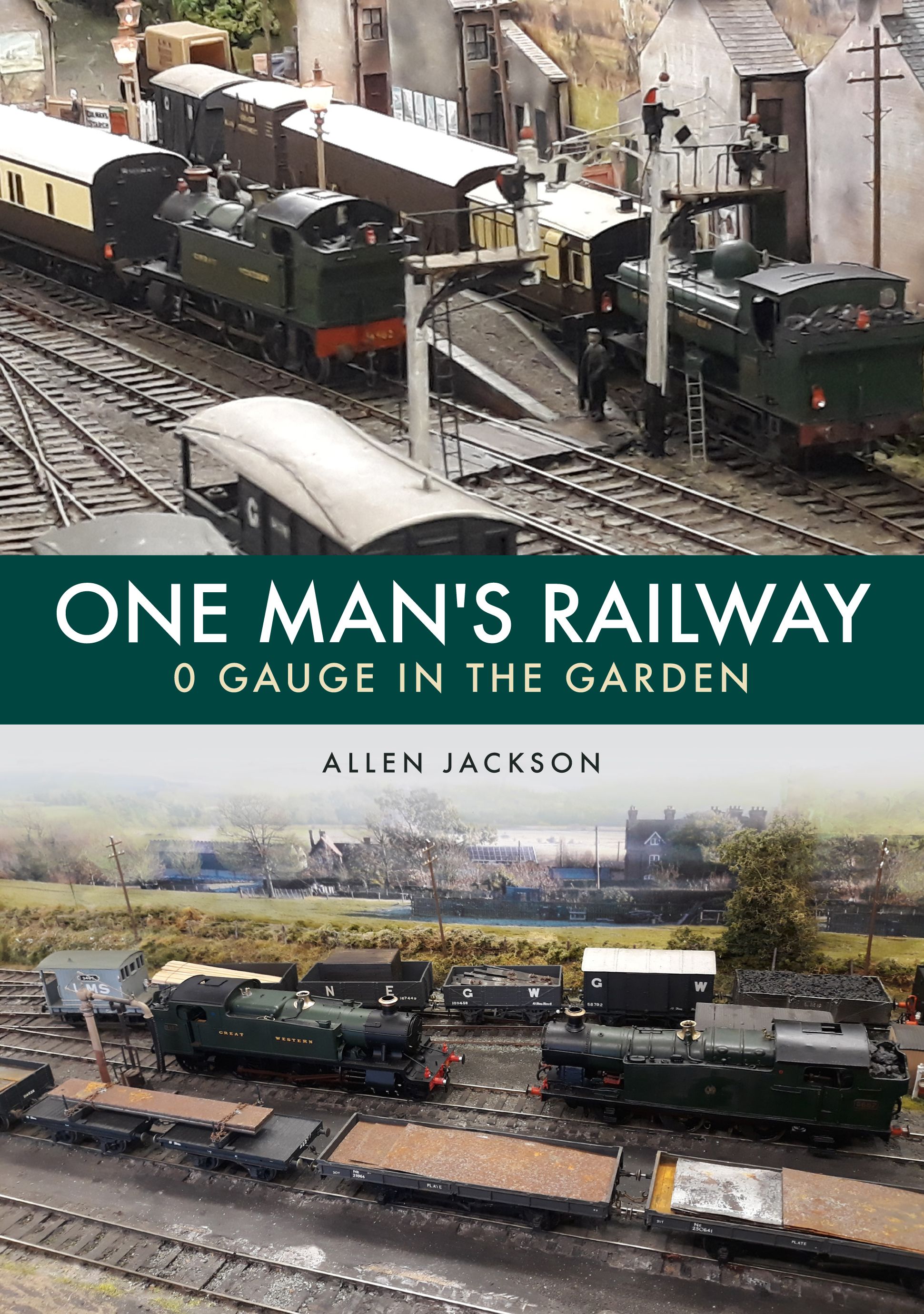
After both an introduction to his O Gauge layout 'Brymbo Junction' and a further piece about the choice of locomotives, author Allen Jackson now goes into detail about the use of semaphore signalling - in prototype and model.
The railway semaphore signal is alive and well in Britain in both the national railway scene and the preserved arena. The semaphore signal kicked off in about 1840 with rudimentary devices like disc and crossbar signals where a different sort of shape was displayed to an engine driver as to go or stop. This was a few years after locomotives were to be preceded by a policeman on foot with a red flag. Mechanical road traffic had similar strictures.
The railways developed in the 19th century in a haphazard manner punctuated by a series of appalling accidents. Eventually the British government in parliament put forward legislation that all railways had to introduce systems that were much safer and relied less on the human element and more on safety devices built into the system. Even then they were given several years to complete the work thanks to the complex nature and size that the railways had become. Included in the parliamentary laws were parts to do with continuous braking fail safe systems. Mostly this concerned vacuum brakes where a pump on the engine had to evacuate a pipe to keep the brakes from coming on. If the pipe broke or there was any other leak the brakes came on, an obvious safety plus. Eventually vacuum brakes would not be powerful enough for high speed heavier trains where air brakes are the norm.
The initial mechanical system that was adopted was the Absolute Block system and, astonishingly, the system is still in use in the more rural parts of Britain as well as preserved railways where speeds and traffic densities are low.
Absolute Block consists of a section of track controlled by semaphore signals originally. A red home signal allows entry into a block and another exit from it. In between there might a yellow distant signal whose only purpose is to tell the driver what position the next red signal is at. This is needed where trains might be travelling at speed and weigh several hundred tons and need advanced warning of when to stop. Signal boxes control a
block section and there would be one signal box per block section originally, meaning there would be about 15,000 signal boxes in Britain in 1947. Trains are passed from block to block by the signal boxes and telegraphic instruments were developed that showed the status of each block to a signal box either side of a particular block so everyone knows where and what trains are doing. So the whole railway would be a network, wifi like, that spanned the country. The absolute block system was only applicable to double track where trains ran in opposite directions on different tracks. On single lines special equipment was developed that prevented a second train entering a single line section until the first had passed safely out of the section. This too is still in operation in Britain on single lines.
The track circuit, please see Figure 1 for an explanatory diagram, was to make the railways even safer. In the 1930s there had been a collision at Welwyn Garden City, north of London, where a train had run into another on the next block section. Interlocking of the next block section with the previous using track circuits meant this could not happen again. Track circuits also help to make single lines safer in that another train cannot be admitted to the single line until the previous train has operated two track circuits next to each other.
The semaphore signal developed into a complex system interlocked with points and other signals and using electrical logic gates to further interlock with track circuits.
Systems were subsequently developed where the signalling was transmitted to the cab of the locomotive and there were no trackside signals. These signals contain a form of remote control where over-speeding or other train driving rule breaking will apply the train brakes automatically. In addition every train is equipped with what the airlines would call a ‘Flight Data Recorder’ where almost every parameter input to the train is recorded and every incident capable of analysis to see what happened. The airlines mostly have the aircraft’s status sent back to a ground station in real time and no doubt the railways will follow suit.
The driverless car has made tentative journeys onto public roads and the Docklands Light Railway in London does not have train crews and is completely automatic. This is fine where routes are simple and works well but signallers and signalling may be required for some time yet on the wider systems.
 Figure 1. A much simplified diagram of a track circuit where a DC current can flow when a railway vehicle wheelset makes a circuit to either show an occupancy light in a signal box/interlocking tower or control colour light signals in concert with other track circuits. In the more modern reality AC circuits are used where each track circuit is allocated a set frequency, rather like an FM radio station.

 Figure 3 (above, left). On the same post is this home and distant signal with the yellow fishtail. The purpose of the distant signal is to give a warning as to the status of the next home signal, a kind of advanced warning for a train that might be moving at 100 mph and weighs 450 tons. Usually the distant signal is on a post of it’s own but when the distance to the next home signal is short then the advanced warning, or not, is given here. The scene is the run up to Sutton Bridge Junction signal box at Shrewsbury in July 2014.
Figure 4 (above, right). Where tracks diverge there is a bracket signal as shown here at Craven Arms on the Shrewsbury to Hereford line in July 2014. The signals themselves carry other messages. The shorter post means that a train will move more slowly into the goods loop and also the shorter arm suggests a non-passenger carrying left diverging track. The taller posts themselves are so a train driver can see the signals beyond a road bridge that crosses the railway. Sighting of signals is an important consideration and whilst the norm in Britain is to have signals on the left of the train that is going forwards they are sometimes placed on the right side of the tracks if a curve or other obstruction would make seeing the signal by the train driver difficult. July 2014.


 O Gauge in the Garden is available to buy through Amberley Books.
https://www.amberley-books.com/one-man-s-railway-0-gauge-in-the-garden.html


